


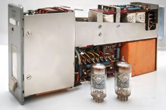


Around the 30s, the guitar began to need more volume in order to “compete” and be heard within the small and large orchestras of the time. Initially, the path taken was to vary the dimensions of the sound boxes. However, this choice was not sufficient and the only solution left was to try to amplify the instrument.


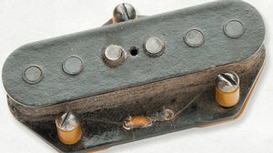
Those were years of great excitement and as often happens, many sought solutions to amplify the guitar. Hence the first prototypes of pickups appeared in parallel.
Lloyd Loar, designer at Gibson from 1920 al 1924, conducted the first experiments by adopting detectors in the vicinity of the ropes. In 1931 Adolf Rickenbacker made the first pickup electromagnetic using it in the guitar Lap steel (also called "Hawaiian guitar"). In 1935 Gibson, which in the meantime had made its first PK, began production of the model ES 150 (ES abbreviation for Eelectric Spanish) and later mandolins and banijos were electrified.
The guitar, until then an acoustic accompaniment instrument, was beginning to be felt seriously. Thus it was that a young guitarist, Charlie christian, began to use the guitar as a solo instrument in jazz. The revolution had begun.
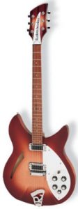
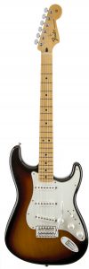
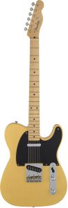


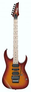


Structure and operation of a Pickup
The sound of a stringed instrument is generated by the vibration of the same as a function of their length, their thickness, their tension and the interaction with the structure of the instrument. The sound is given by the fundamental vibration frequency of the string plus a series of harmonics which, when combined with the fundamental, characterize the timbre of the instrument. This is precisely what we want to capture and amplify with the pickups.
Brief notes on the operating principles of a pickup
The pickups consist of a permanent magnet that generates a magnetic field and a winding around the magnet formed by numerous coils of wire and which forms an electric coil.

We can easily visualize this concept through a simple experiment. Take a magnet, a sheet of paper and some iron filings. Place the magnet under the sheet of paper and spread the iron filings over it. The iron filings should be arranged more or less neatly between the south pole and the north pole of the magnet as shown. You can thus easily observe the lines of force of the magnetic field generated by a magnet.
Schematic of a Pickup

Let's go back to the guitar now. The vibration of the string causes a variation in the magnetic field which, due to the effect of electromagnetism, will generate an electric current in the winding; this current will then be transmitted to the amplifier. The perturbation of the magnetic field will depend on the oscillation of the string (fundamental frequency / harmonics / speed of movement of the string etc.) and consequently the induced current in the coil will be the mirror of the vibration.
Characteristics of a PK
According to the magnetic material with which they are built, the PK are divided into AlNiCo e Ceramics. Instead, in relation to the number of coils, the pickups differ in Single coil (single coil) ed humbuckers (double coil).
MAGNET
The AlNiCo it is a ferromagnetic alloy containing iron, aluminum, nickel and cobalt, used to build permanent magnets. To obtain different AlNiCo alloys it is sufficient to change the proportion between the constituents. In this way we obtain AlNiCo II, AlNiCo III, AlNiCo IV, AlNiCo V etc ...
Among these, the most used are AlNiCo V and II. The Alnico V alloy is made up of cobalt (24%), nickel (14%), aluminum (8%), copper (3%) and iron (the remaining part).
Alnico V generates a stronger magnetic field than AlNiCo II and for this reason it is considered excellent for bridge pickups, where there is generally less vibration of the strings. It is particularly suitable for a rather aggressive sound.
With the same turns and magnetic bar dimensions, in a PK in AlNiCo the lower the degree (I, II, IV, V) the lower the magnetic field generated and consequently the output signal; this corresponds to a slightly “softer” and less defined tone in the high frequencies.
In reality, as we will see later, the chemical constitution of a PK magnet is only one of the elements that determine its sound.
CERAMIC
I ceramic magnets, less expensive than AlNiCo, are obtained by mixing clay with ferrous materials (Barium ferrite).
Ceramic PKs have excellent magnetic strength; they are generally considered more aggressive and mostly indicated for distorted sounds. However, as previously mentioned, there are many variables that affect the final sound of a PK: type of magnet, number of coils (SC or HH), thickness of the wire used for winding, number of turns, quality of the wire, material wire insulator etc.
We can find on the market excellent well-designed ceramic PK and bad AlNiCo and vice versa. To this we must add that the musical style, personal taste and way of playing are further factors that can influence the choice.
Over the years, the search for ever more efficient pick-ups has led to an evolution of magnets both in terms of their chemical composition and in terms of shape and arrangement.
Thus we find pickups with bar magnets inserted directly into the coils; pick-ups that have magnets under the coils and soft iron cores (usually screws) inside them, allowing for accurate adjustments for each string, etc.
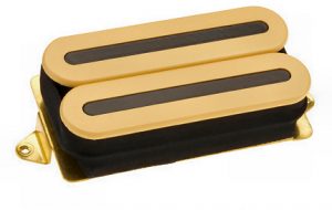
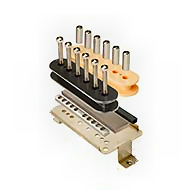

Coil / Winding / Wire
Summary of some fundamental concepts:
* The greater the number of turns of the winding, the greater the output volume
* The greater the number of turns, the greater the inductance
* The greater the inductance, the greater the cut of the high frequencies
* The smaller the wire section, the greater the resistance
* The greater the thickness of the wire section, the less resistance, inductance and number of turns per unit of volume will be
* The fewer the number of turns, the lower the output volume will be.
As often happens in electroacoustics, the choice of a solution is always the result of a compromise, that is, it will be necessary to find the right mix between all the variables.
A inductance placed in series to a circuit it represents a XNUMXst order low pass filter. As many of you know, inductances are used in passive crossover filters of loudspeakers to "cut" the frequencies directed to the various speakers. We will address this topic in detail shortly, because it is very important.
Wire section and resistance
As I already had the opportunity to illustrate in my previous article "Cables & Music"To resistance R of a wire is directly proportional to its length and is inversely proportional to its section and can be calculated using the Ohm's second law.

As a result, a thin wire with many windings will turn out to be very long and this will affect its strength.
The most commonly used number of turns is between 6000 e 7500 with a wire gauge of 42 43 AWG (Aamerican Wire Gauge) The most used wire sections are AWG 42 (which corresponds to about 0.063mm) and AWG 43 (0.056mm), although it can go up to AWG 47 (0.036mm).
From an electrical point of view the pickup can be represented by the following equivalent circuit:

The coil can be described electrically as inductance L in series, with an Ohmic resistance R and parallel to a winding capacitance C
For the description of a humbucker, two of these circuits must be connected in series. If both coils have virtually identical properties, the same replacement circuit can be used. However, double the inductance and resistance values and half the capacitance value should be used compared to the single coil model.
To this we must now add the external circuit to the pickup consisting of a resistance (the volume and tone potentiometer of the guitar and any other resistance) and the capacitance (due to the capacitance of the cable). The capacity of the cable is very important and should not be neglected.
For more details on the electrical characteristics of the cables (resistance, capacitance and inductance) I refer you to my previous articles on cables published on Age Of Audio
Cables and Music
Cables and Music part two
Let's now schematize a Total Equivalent Circuit: Pickup + External Circuit

This simplified scheme of a pickup and its external circuit is equivalent to a 2nd order low pass audio filter which will therefore have its own cut-off frequency and a very precise resonance peak.
Here the value of the inductance, which is expressed in Henries, assumes particular importance. This value can give us some first indications on the acoustic behavior of the pickup. Inductance depends on the number of turns of the wire making up the coil, on the magnetic material in the coil, on the winding density and on the overall geometry of the coil.
Like other types of filters, the total circuit will have a cutoff frequency (fc) where the response will have an attenuation of -3 dB. Beyond the fc, the response falls with a slope of 12 dB per octave. Just before the fc we find a resonance peak.

Generic response example
Knowing the frequency and height of the resonance peak, it is possible to have an idea about the sonic characteristics of a pick-up.
In most commercially available pickups, the resonant frequency varies between 2000 and 6800 Hz, a range to which the human ear is very sensitive. The feeling when listening to pickups with cutoff fequency at approx 2.000 Hz is that of a warm sound, a 3.000 Hz present, a 4.000 Hz penetrating ea 5.000 Hz rather subtle but very detailed. The sound also depends a lot on the height of the peak, of course.
In most pickups the peak height varies by a few dB and has been observed to depend mainly on the magnetic material of the coil, the external resistive load and the metal case (without the casing it is higher and many guitarists prefer it).
The resonant frequency depends on both the inductance L (generally between 1 and 10 Henries) and the capacitance C. C is the sum of the winding capacitance of the coil (usually around 80 - 200 pF) and the capacitance of the cable (around 300 - 1.000 pF).
Since guitar cables have different capacities, using different cables with the same pickup will change the resonant frequency and therefore the overall sound.
The first pickups were a single coil, consisting of a single coil that wrapped a permanent magnet. However, as the coils are extremely sensitive to electromagnetic interference caused by alternating magnetic fields, these pick-ups were triggered not only by the vibration of the string, but also by anything that had the characteristics of an electric wave (alternating current 50 / 60Hz, neon lights etc.) generating noises and hums.
Humbucker pickup
Just to solve this kind of problems in the 1956 Seth lover, an employee of Gibson, patented the first PAF Humbucker (Licensed Applied For, i.e. pending patent application. From the presentation of the patent to the obtaining of the same, some time passed during which however the commercialization began with the indication PAF). To be honest, the first humbucker pick-up was invented in 1934 by Joseph Raymond "Ray" Butts, who started working on his own pickup independently and in parallel with Seth Lover. The first to obtain the patent was Ray Butts (patent no. 2.892.371) followed by Seth Lover (patent no. 2.896.491). Despite this, Ray Butts was never recognized as the one who invented and produced the first humbucker pickup. As mentioned earlier, the coils are very sensitive to any type of electromagnetic interference caused by alternating magnetic fields. The voltage induced in a coil has its own direction which is defined by the direction of the winding (clockwise or counterclockwise) and by the orientation of the permanent magnets. The humbucker consists of two coils wound in two opposite directions and magnets also arranged in two different directions. How is noise elimination done? Very simply we can summarize that the two coupled coils are connected in series and in phase opposition, so that the noise in the signal of one coil is canceled by the same signal in phase opposition in the other. The use of two coils obviously implies an increase in the number of turns, a greater length of the wire, a greater resistance and a lower frequency response.
In next episode we will examine in more depth the sound characteristics of the pick-ups based on their construction characteristics and their positioning. Obviously, as mentioned in the title, we will also examine the passive component, i.e. potentiometers and capacitors which, together with the pick-ups, contribute to the formation of the circuit and contribute significantly to the final sound.
Good music and happy holidays to all
the next
Bibliography
Musical Instruments N ° 116
Musical Instruments N ° 193
Musical Instruments N ° 194
Musical Instruments N ° 195
Musical Instruments N ° 196
Helmuth Lemme: Electric Guitar Sound Secrets and Technology
Dave Hunter - The Guitar Pickup Handbook: The Start of Your Sound
Wikipedia
Agreement.it
Build your Guitar.com Helmuth EW Lemme The Secrets of Electric Guitar Pickups


